
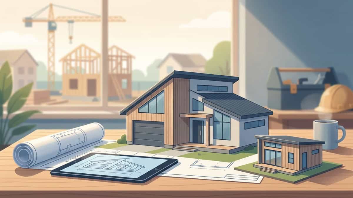
A complete house construction design translates architectural concepts into structural blueprints, engineering calculations, and code-compliant building plans. It unifies spatial layouts, foundation specifications, load-bearing framing, and utility pathways into a single coordinated document set. Getting this design right before breaking ground ensures your project passes municipal permitting, avoids structural rework, and proceeds on schedule.

What Is House Construction Design?
House construction design is the technical and architectural roadmap that governs every phase of a residential build. While an architectural sketch focuses on aesthetics and room flow, a construction design package details how the structure actually stands, resists environmental loads, and functions day-to-day.
When we create a buildable design, we bridge the gap between creative floor planning and physical job-site execution. A sketch might show a wide-open living area, but the construction design calculates the specific steel I-beam or engineered glulam header required to carry the roof load without intermediate posts.
Every design decision directly impacts construction sequencing:
- Foundation Integration: Footings and slab designs must match local soil plasticity and frost lines.
- Structural Framing: Wall studs, floor joists, and roof rafters must align to transfer loads safely down to the foundation.
- Utility Routing: Mechanical chases, plumbing drops, and electrical runs must be integrated directly into framing plans to avoid cutting structural members later.
Selecting the right design strategy early helps you decide whether to hire an architect vs design build firm for custom homes to manage your drawings and structural sign-offs.
Core Components of a Complete House Construction Plan
A buildable construction plan set consists of coordinated sheets. Municipal building departments require these drawings to verify structural integrity, fire safety, and energy code compliance before issuing a building permit.
| Plan Sheet | Core Purpose | Critical Information Included |
|---|---|---|
| Site Plan | Property orientation & boundary verification | Property lines, setbacks, easements, finished floor elevation, drainage flow |
| Floor Plans | Spatial layout & interior dimensions | Wall locations, window and door schedules, room sizes, fixture layouts |
| Foundation Plan | Substructure engineering | Concrete slab details, footing depths, rebar spacing, grade-beam sizing |
| Framing Plan | Structural load pathways | Stud spacing, header sizes, shear walls, roof truss layout, floor joist spans |
| MEP Schematics | Mechanical, electrical & plumbing paths | HVAC duct sizing, electrical service panel location, drain-waste-vent lines |
| Elevations & Sections | Vertical relationships & envelope | Floor-to-ceiling heights, roof pitch, exterior cladding, insulation assemblies |
Structural Framing and Engineering
Framing sheets indicate the exact lumber species, engineered wood grades, or steel gauges required. When planning structural openings or long spans, plans detail continuous load paths from the roof ridge down to the ground. If you are retrofitting or reconfiguring an existing layout, consult our guide on removing load bearing walls to understand how temporary shoring and replacement beams work.
Mechanical, Electrical, and Plumbing (MEP) Layouts
Plumbing stacks require dedicated vertical wall cavities, usually built with deeper framing studs than standard partition walls. Mechanical drawings map supply and return air trunks through attic framing or dropped soffits so that duct runs do not collide with structural floor trusses.
Choosing the Right Layout: Custom Homes, Additions, and ADUs
The layout you choose dictates framing complexity, foundation square footage, and interior lifestyle flow. Whether you are executing a ground-up build, a secondary suite, or a detached structure, the floor plan must balance usable living space with practical structural support.
PRO Construction provides Accessory Dwelling Units (ADU), Garage Conversions, Garage Builds for Homeowners in Keller, TX and surrounding communities seeking additional living space, rental income, or guest accommodations.
+-------------------------------------------------------------------+
|                        SPLIT-BEDROOM LAYOUT                       |
|  +---------------+     +--------------------+     +---------------+
|  |   Secondary   |     |    Open Living     |     |    Primary    |
|  |   Bedrooms    | <-> |    Dining & Kitchen| <-> |    Suite      |
|  |   & Bath      |     |    (Central Zone)  |     |   (Private)   |
|  +---------------+     +--------------------+     +---------------+
+-------------------------------------------------------------------+
Open-Concept vs. Split-Bedroom Layouts
Open-concept designs remove partition walls between the kitchen, dining, and main living areas to maximize natural sightlines. While visually spacious, these layouts demand larger structural beams to span wide distances without load-bearing support walls.
Split-bedroom floor plans place secondary bedrooms on the opposite side of the home from the primary suite, separated by the central living space. This arrangement creates built-in acoustic privacy without requiring long, wasted hallway corridors. For full-scale builds, review building a custom home the complete guide to evaluate how footprint shapes influence construction costs.
Designing Compact Footprints for ADUs and Suites
Compact footprints demand disciplined spatial planning. When laying out a secondary suite or detached structure, every square foot must serve multiple functions:
- Stacked Wet Walls: Align kitchen plumbing and bathroom supply lines along a shared wall to reduce pipe runs and material costs.
- Pocket and Barn Doors: Replace traditional swing doors to reclaim clearance space in narrow bedrooms and bathrooms.
- Dedicated Utility Closets: Incorporate tankless water heaters and ductless mini-split systems that fit within standard wall depths or compact closets.
For regional regulations and planning steps, explore everything you need to know about building an adu in north texas and evaluate our comparison between an adu guest house vs home addition. If you are considering alternative structural framing methods, read our guides on building a barndominium in Texas and modular homes explained.
The Step-by-Step House Construction Design Process
Developing an efficient house construction design involves progressive refinement, turning broad ideas into engineered construction documents.
[ Step 1: Site Evaluation ]
          │
          ▼
[ Step 2: Schematic Drafting ]
          │
          ▼
[ Step 3: Structural Engineering & Permitting ]
          │
          ▼
[ Step 4: Pre-Construction Alignment ]
1. Site Evaluation and Zoning Constraints
Before drafting begins, the building site must be surveyed. We check property boundary pins, calculate building envelope setbacks, identify underground utility easements, and inspect surface drainage patterns. If you are shopping for property, our guide on how to find and evaluate building lots in keller tx outlines how zoning and soil profiles impact your foundation choices.
2. Schematic Drafting
During schematic design, preliminary floor layouts and exterior elevations are created. This step defines room dimensions, ceiling heights, door and window placements, and exterior cladding styles.
3. Structural Engineering and Permit Documentation
Once the floor plan is locked, a licensed structural engineer reviews the plans. They specify foundation reinforcement, beam sizes, and wind-load connections required by local building codes. Complete construction sets are assembled for municipal plan review.
4. Pre-Construction Alignment
Before framing starts, the architectural drawings are cross-referenced with vendor material availability, finish selections, and subcontractor scopes. Using established design build project management ensures that the windows, trusses, and mechanical units specified on paper arrive on-site without supply delays. Use the ultimate residential construction checklist to confirm every detail is accounted for before breaking ground.
Common Design Mistakes That Cause Construction Delays
Design errors caught during active framing or rough-in inspections lead to schedule halts and costly plan revisions.
┌─────────────────────────────────────────────────────────────┐
│                 COMMON DESIGN FAILURE POINTS                │
├──────────────────────────────┬──────────────────────────────┤
│ 1. Boundary & Setbacks       │ 2. MEP Chases & Clearances   │
│ Ignored easements require    │ Missing mechanical chases    │
│ site redesigns or variances. │ force structural header cuts.│
├──────────────────────────────┴──────────────────────────────┤
│ 3. Unadapted Stock Plans                                    │
│ Generic internet plans fail local wind, soil, and snow loads│
└─────────────────────────────────────────────────────────────┘- Designing Outside Setbacks and Easements: Drawing an addition or detached garage that crosses municipal side setbacks or utility easements will trigger an instant permit rejection, forcing a complete redesign of the foundation footprint.
- Omitting Dedicated Mechanical Chases: Floor plans that do not account for vertical plumbing stacks, electrical panels, and HVAC return ducts force trades to notch structural joists and studs, weakening the frame and failing rough framing inspections.
- Using Unmodified Stock Floor Plans: Stock plans downloaded from online catalogs rarely match localized building codes, active soil requirements, or wind-shear criteria. Every stock plan must be adjusted and sealed by an engineer familiar with your specific region.
Frequently Asked Questions
What is the difference between a floor plan and a full construction design set?
A floor plan is a two-dimensional layout showing room arrangements, walls, and doorway positions. A full construction design set includes structural engineering, foundation specifications, framing cross-sections, elevation views, and mechanical, electrical, and plumbing schematics required for building permits and on-site assembly.
Can I build directly from stock house plans purchased online?
Stock plans provide an architectural starting point, but they cannot be submitted directly for building permits in most jurisdictions. They must be modified by a design professional or engineer to comply with local wind loads, seismic zones, regional energy codes, and site-specific soil bearing conditions.
How does site topography influence house construction design?
Topography determines your foundation design, finished floor elevations, and stormwater management systems. Sloped lots often require stepped footings, stem walls, or walkout basement foundations, while flat lots demand engineered grading to direct water away from the structure. A solid house construction design always adapts to the natural contours of the land.